L. Inductor
Symbol Names: IND, IND2
Syntax: Lxxx n+ n- <inductance> [ic=<value>]
+ [Rser=<value>] [Rpar=<value>]
+ [Cpar=<value>] [m=<value>] [temp=<value>]
It is possible to specify an equivalent series resistance, series inductances, parallel resistance and parallel shut capacitance. The equivalent circuit is given below:

Inductor Instance Parameters
| Name | Description |
| Rser | Equivalent series resistance |
| Rpar | Equivalent parallel resistance |
| Cpar | Equivalent parallel capacitance |
| m | Number of parallel units |
| ic | Initial current(used only if uic flagged on the .tran card) |
| tc1 | Linear inductance temperature coeff. |
| Tc1 | Quadratic inductance temperature coeff. |
| temp | Instance temp |
It is better to include the device parasitics Rpar, Rser, and Cpar in the inductor than to explicitly draft them. LTspice uses proprietary circuit simulation technology to simulate this physical inductor without any internal nodes. This makes the simulation matrix smaller, faster to compute and less likely to be singular over all time-step sizes.
By default, LTspice will supply losses to inductors to aid SMPS transient analysis. For SMPS, these losses are of usually of no consequence, but may be turned off if desired. On the "Tools=> Control Panel=>Hacks!" page, uncheck "Supply a min. inductor damping if no Rpar is given." This setting will be remembered between invocations of the program. There is also a default series resistance of 1 milliohm for inductors that aren't mentioned in a mutual inductance statement. This Rser allows LTspice XVII to integrate the inductance as a Norton equivalent circuit instead of Thevenin equivalent in order to reduce the size of the circuit's linearized matrix. If you don't want LTspice to introduce this minimum resistance, you must explicitly set Rser=0 for that inductor. This will require LTspice to use the more cumbersome Thevenin equivalent of the inductor during transient analysis.
There are two forms of non-linear inductors available in LTspice. One is a behavioral inductance specified with an expression for the flux. The inductor's current is referred to by the keyword "x" in the expression. Below is an example in a netlist.
*
L1 N001 0 Flux=1m*tanh(5*x)
I1 0 N001 PWL(0 0 1 1)
.tran 1
.end
In the above example, I1 supplies a unity dI/dT so that the inductance can be read off as the voltage on node N001.
The other non-linear inductor available in LTspice is a hysteretic core model based on a model first proposed in by John Chan et la. in IEEE Transactions On Computer-Aided Design, Vol. 10. No. 4, April 1991 but extended with the methods in United States Patent 7,502,723. This model defines the hysteresis loop with only three parameters:
| Name | Description | Units |
| Hc | Coercive force | Amp-turns/meter |
| Br | Remnant flux density | Tesla |
| Bs | Saturation flux density | Tesla |
The upper and lower branches of the hysteresis major loop are given by

and

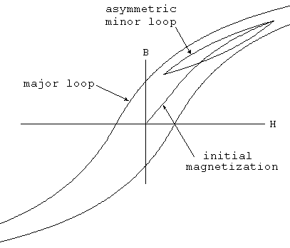
These functions are plotted in following figure. Hc and Br are the intersections of the major hysteresis loop with the H- and B-axes. Bs is the B-axis intersection of the asymptotic line, Bsat(H) = Bs + μ0 · H, approached as H goes to infinity.

The initial magnetization curve is given by
Bmag(H) = .5 · (Bup(H) + Bdn(H))
Minor loops are obtained by various translations of the above equations per the cited reference. The core's absolute and differential permeabilities are a function of H and the history of values of H. The plot below shows the path taken by an asymmetrical minor loop for a typical power ferrite(Hc=16 A-turns/m, Bs=.44T, Br= .10T).

In addition to the core property parameters Hc, Br, and Bs, mechanical dimensions of the core are required:
| Name | Description | Units |
| Lm | Magnetic Length(excl. gap) | meter |
| Lg | Length of gap | meter |
| A | Cross sectional area | meter**2 |
| N | Number of turns | - |
Note that if specifying a non-zero gap the magnetic field, H, is not proportional to the current in the windings. LTspice solves for the magnetic fields in the core and gap under the assumption of uniform cross sectional area and thin or uniformly distributed gap.
Below is an example that shows inductance vs. current for L1, an inductor wound on a gapped core. You can read out the inductance as V(n001) since current source I1 supplies a unity dI/dt. The core follows the initial magnetization curve, so you can see that the permeability first increases from the initial value as the current is ramped and then drops as it saturates. Since the gap makes the inductance insensitive to the exact permeability of the core, you have to really zoom in on V(n001) to see that it does increase. The peak is when H inside the core is equal to its Hc.
*
L1 N001 0 Hc=16. Bs=.44 Br=.10 A=0.0000251
+ Lm=0.0198 Lg=0.0006858 N=1000
I1 0 N001 PWL(0 0 1 1)
.tran .5
.options maxstep=10u
.end