Basic Schematic Editing
The schematic capture program is used to create new schematics or modify the example circuits provided. The circuit size and depth of hierarchy is limited only by computer resources.
The program ships with over 2,000 symbols. These symbols cover most of LTC's power ICs, opamps, comparators, and many general-purpose devices for circuit design. You can also draw your own symbols for devices you wish to import into the program.
LTspice schematic editing is a "verb-noun" interface instead of "noun-verb." That means that instead of first selecting objects(the nouns) to move, drag, copy, or delete(the verbs); you first select the action and then the object. Hence, when you wish to move, mirror, rotate, drag or delete objects, first select the move, drag or delete command. Then you can select an object by clicking on it. You can select multiple objects by dragging a box about them. The program will stay in the move, drag, or delete mode until the right mouse button is clicked or the Esc key is pressed. The verb-noun approach reduces the amount of mouse syntax required to edit schematics. Once mastered, it allows the user to draft faster in LTspice than is possible with pencil and paper.
Undo: Undo the last command.
Redo: Redo the last Undo command.
Text: Place text on the schematic. This merely annotates the schematic with information. This text has no electrical impact on the circuit.
SPICE Directive: Place text on the schematic that will be included in the netlist. This lets you mix schematic capture with a SPICE netlist. It lets you set simulation options, include files that contain models, define new models, or use any other valid SPICE commands. You can even use it to run a subcircuit that you don't have a symbol for by stating an instance of the model(a SPICE command that begins with and 'X') on the schematic and including the definition.
SPICE Analysis: Enter/edit the simulation command.
Resistor: Place a new resistor on the schematic.
Capacitor: Place a new capacitor on the schematic.
Inductor: Place a new inductor on the schematic.
Diode: Place a new diode on the schematic.
Component: Place a new component on the schematic. The command brings up a dialog that lets you browse and preview the symbol database. This is a more general form of the Resistor, Capacitor, Inductor, and Diode commands.
Rotate: Rotate the sprited objects. Note this is grayed out when there are no objects sprited.
Mirror: Mirror the sprited objects. Note this is grayed out when there are no objects sprited.
Draw Wire: Click the left mouse button to start a wire. Each mouse click will define a new wire segment. Click on an existing wire segment to join the new wire with an existing one. Right click once to cancel the current wire. Right click again to quit this command. You can draw wires through components such as resistors. The wire will automatically be cut such that the resistor is now in series with the wire.
Label Net: Specify the name of a node so an arbitrary one isn't generated by the netlister for this node.
Place GND: Place a GROUND symbol. This is node "0", the global circuit common.
Delete: Delete objects by clicking on them or dragging a box around them.
Duplicate: Duplicate objects by clicking on them or dragging a box around them. You can copy from one schematic to another if they are both opened in the same invocation of LTspice XVII. Start the Duplicate command in the window of the first schematic. Then make the second schematic the active window and type Ctrl-V.
Move: Click on or drag a box around the objects you wish to move. Then you can move those objects to a new location.
Paste: It is enabled in a new schematic window when objects were already selected with the 'Duplicate' command.
Drag: Click on or drag a box around the objects you wish to drag. Then you can move those objects to a new location and the attached the wires are rubber-band with the new location.
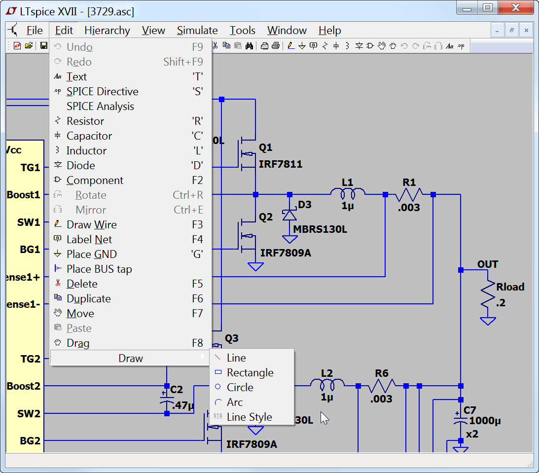
Draw=>Line: Draw a line on the schematic. Such lines have no electrical impact on the circuit, but can be useful for annotating the circuit with notes.
Draw=>Rectangle: Draw a rectangle on the schematic. This rectangle has no electrical impact on the circuit, but can be useful for annotating the circuit with notes.
Draw=>Circle: Draw a circle on the schematic. This circle has no electrical impact on the circuit, but can be useful for annotating the circuit with notes.
Draw=>Arc: Draw an arc on the schematic. This arc has no electrical impact on the circuit, but can be useful for annotating the circuit with notes.
NOTE: The graphical annotations to the schematic; lines, rectangles, circles, and arcs; snap by default to the same grid as the used for electrical contacts of wires and pins. Hold down the control key while positioning these to defeat this snap.