Simulating Transformers
How do I simulate a transformer?
Draft coupled inductors as independent inductors and then add a mutual inductance statement placed as a SPICE directive on the schematic. See the section on mutual Inductance for more information. Inductors participating in a mutual inductance will be drawn with a phasing dot.
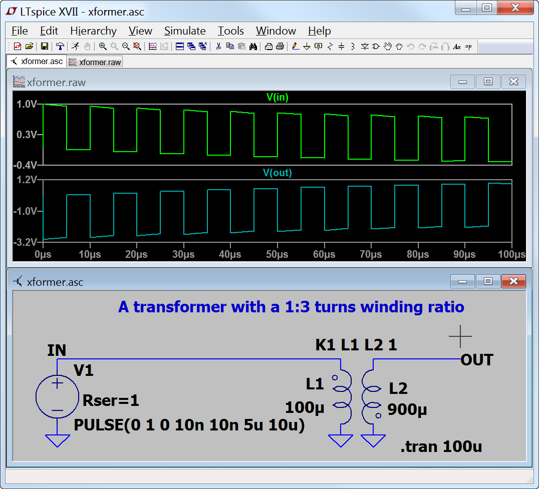
The following example illustrates a transformer with 1:3 turns ratio (one to nine inductance ratio) with a square wave input. The mutual coupling coefficient is set to 1 to model a transformer with no leakage inductance.
No, that is too easy. Don't you have anything more complicated?
Sure:
i) Measure winding L's with a DC LCR meter. Use these values directly in simulation.
ii) Measure winding ESR with an ohmmeter. Use twice these values in simulation since the resistance at frequency is higher than the DC value. My experience with ferrite and switchers is that it is usually nearly a factor of two higher.
iii) Short all but the most inductive winding and measure the leakage inductance with the DC LCR meter. Adjust the coupling coefficient to match this, or for the case of two windings:
K = sqrt(1-Lleak/sqrt(L1*L2))
Lleak = sqrt(L1*L2)*(1-K*K)
iv) Find the transformer's resonate frequency and Q. Specify a Cpar and Rpar for the most inductive winding to match this resonance.
v) Enjoy.
What about non-linear Transformers?
Please see the example installed as %HOMEPATH%\Documents\LTspiceXVII\examples\Educational\NonLinearTransformer.asc